Monday, July 6, 2009

Thermoelectric Temperature Controller - Part 5

From many great inputs from various sources on Sparkfun.com, allaboutcircuits.com and comments on this blog, I've come up with some improvements to the control circuitry. Those improvements are...
  1. PWM control of the driving MOSFET instead of a filtered linear voltage control
  2. An H-bridge controller to allow for heating as well as cooling via digital control
  3. Reducing outputs used by the micro-controller to free them up for anything else, or to use a smaller micro-controller
The first thing I noticed when runnning the previous circuits shown in Part 3 was that the IRF510 MOSFET was running very hot when it was not being driven at the saturation voltage. This is because MOSFETs are most efficient when run at full on. In the circuit in part 3, R8, R9 and C4 were filtering the PWM from the micro-controller and driving the MOSFET at a linear voltage. The MOSFET really needed to be run at either a full-on or full-off mode, i.e. true PWM. To accomplish this, get rid of R8, R9 and C4 and drive the MOSFET with a low-impedance circuit.


Next, I wanted to add the ability to heat as well as cool. To do this with a peltier device, all you need to do it change the polarity (reverse the current) to the peltier. This is commonly done to control motors to make them go in forward and reverse. I looked around for a cheap and good motor controller and found a great one at pololu.com called the MC33887 Motor Driver Carrier. You can also get it here at Sparkfun.com. This motor driver can handle up to 5A, so it can only be comfortably used in the soda-can cooling prototype. In the future I will be identifying a motor controller that can be used to cool a fermentation carboy.

Also, this motor controller has a useful function which allows monitoring of the current flowing through the controller. This can be used as a feedback control, however, for my purposes, I will be using this only as a current monitor.

To test the H-bridge along with peltier device, I hooked up the following simple circuit. For the RAW(~12V) supply, I used the +12V output from an old computer power supply. I also used the regulated 5V from to drive the micro-controller. Note: the download circuit is not shown, also ENAB is tied to 5V and D1 is tied to ground. The potentiometer was a 100K pot.


Here is the program code to run the above simple circuit.

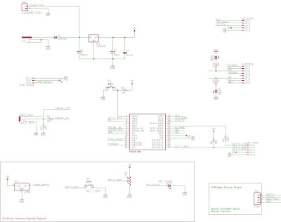
The circuit below shows how I will be implementing all these changes. I'm still using the same LED display board that I developed in Part 3. I am still developing the program code to run the circuit below, but it should be pretty straight forward and will involve some additional items added to the above program code to control the LED driver display, perform loop feedback control and get inputs from the temperature setting function.


In the next post, I will have the program code ready as well as the prototype of the soda can cooler completed. From there, I will do some actual cooling/heating and record some data to show it's performance.

Just to reiterate, these circuits have been developed for a small prototype of a soda can cooler/heater. I hope to scale everything up and fabricate a temperature controlled chamber for beer fermentation carboys. In these later discussions, I will post some things I've come across to drive multiple peltier devices efficiently.

Monday, June 1, 2009

Beer Labels...

So I was messing around with photoshop and a picture of my cats and came up with a beer label for the new batch of homebrew. Named after one of my favorite albums.


I think, however, that my beer label will go by the wayside as I start looking into home kegging systems. The thought of having to wash all those bottles again is daunting...

Friday, May 15, 2009

Thermoelectric Temperature Controller - Part 4

As promised, here is the program code for use with the PICAXE and it's programming editor: Program Code

The verbal description of this program is this:
  1. Configure the display
  2. Read the temperature from the LM34
  3. Display the temperature on the LED display
  4. If the temperature set point is below the current temp, then perform a PWM command and turn on the Peltier device. The amount of drive is proportional to the error between the set point and current temp.
  5. If the temperature set point is above the current temp, then turn the PWM off.
  6. If at any point, the temperature set point button is pressed, flash the set point LED and enter the set temp mode. Read the temperature set point from the potentiometer. Press and release the button quickly to exit the set temp mode.
  7. Keep looping.
Some points within the program that may not be so obvious. First, when we read the temperature from the LM34, the picaxe reads the analog voltage and converts it to a digital value with ten bits of resolution. This means that the value has 2^10 or 1024 divisions. The digital value can then be calculated back into a voltage in mV within our program. The ADC is converting based on a 5V range, or 5000 mV. This means that a digital value of 0 is equal to 0 mV and a digital value of 1024 is equal to 5000 mV. Taking this further, each digital division is equivalent to 5000/1024, or 4.88 mV. By the way, 4.88 mV is the same as 0.488 deg F, so the resolution of our program is ~0.5 deg F. You can see from the program that when we mulitply the digital value by 4.88, we will in essence be calculating the temperature in deg F mulitplied by ten. Since the temperature is read in tens of millivolts, the actual whole number value of the temperature can be read once we divide TE_Temp_10 by 10.

I will update this discussion of my code at a later time, hopefully the code will speak for itself. Enjoy!

Tuesday, May 12, 2009

Thermoelectric Temperature Controller - Part 3


Since my last post I've have worked on developing a prototype small scale version of a wort fermentation cooler. This was mainly to prevent mistakes from becoming too costly and work out any kinks on the model before scaling up. In the small-scale model, I will simulate a fermentation vessel as a soda can - basically this will become a desktop soda cooler. If you are innovative and modify the circuit to allow for a change in the polarity (or just switch the leads) across the Peltier device, you could also have this work as a coffee warmer as well. This is one of the great things about these devices, the ability to use them for both cooling and heating.

This post will mainly focus on the control system and interface that I have developed for controlling the temperature of the vessel of interest. When controlling the temperature, the only way to go is by setting a temperature set-point and using loop feedback control. The algorithm for controlling the device to reach this temperature can be quite a bit more involved, ranging from proportional control up to proportional-integrative-differential (PID) and even on to fuzzy logic. Initially, for my system I have elected to go for proportional control since it is one of the simplest forms of control and it allows for the opportunity to just add on to it if it seems inadequate.

For the size of peltier device that I am using (CP40336, Digikey part no.
102-1671-ND
), I designed a circuit that could handle its max current of 3.9 amps. This circuit that can not, however, handle currents that would be required by my large fermentation cooling system, which may be in the 20+ peak amps range. The current to the peltier device is controlled by the IRF510 MOSFET (shown in circle A below) and has a max continous drain current of 4 amps, with a pulse drain of 20 amps. Note that these types of devices will need a heat sink as they get very hot. I chose this device because it is voltage controlled, which means it uses much less current than current controlled transistors, such as BJTs and it can be much simpler to control since we can control voltage straight out of the microcontroller. In addition, this device is also logic level controlled, meaning that I can control it with voltages that are in the range of my 12 V power supply. I will be using a AC-DC power supply that can provide a few amps like this one: VM 80W12.

The amplifier circuit shown in circle B allows the 0-5 V PWM voltage signal from the microcontroller to be pumped up to voltages almost as high as those supplied to the op-amp, in this case, close to 12V. There is some loss across the device and in my case was around 1.5 volts, meaning that the op-amp can put out about 10.5 V. This particular circuit is called a voltage follower. The circuit tries to match the voltage on pin 2 and pin 3. Since pin 2 is connected to a voltage divider circuit (the voltage on pin 2 is halfway between ground and the output of the device) it always sees a value that is half the output. This leads to the output being double the voltage of the input. This may sound confusing if you are a beginner to this so here is an example: If you supply a voltage of 3 V to pin 3, the device wants to match make pin 2 match this value. It does this by increasing the output voltage until these match or the device is maxed out. In our example, the output will reach 6 volts at which point pin 2 will be at 3 volts - now pin 2 and pin 3 match. The equation for this relation is shown below for reference. The ratio of the resistors can be modified to give you a range of ratios. If you want to look into this further, look for "non-inverting DC gain" amplifier circuits.


Since we are driving the op-amp with pulse width modulation from the microcontroller, the signal needs to be smoothed out a bit to give a near analogue signal. This is the function of the 0.68 uF capacitor - that's what capacitors are really good for, smoothing out voltages since they act much like a damper in a suspension system.

To control this circuit, I decided to go with a PICAXE 28-pin microcontroller (shown at left) since this is a cheap and pretty easy to use beginner microcontroller. It had the features that I desired in controlling this circuit, mainly an analog-to-digital converter and pulse-width modulation control. This size of PIC may be overkill, but I plan on using it for various other projects as well. It also has plenty of output and input pins should I want to add more sensors, LEDs or other devices I want to control such as fans.

The feedback to the controller is supplied by means of an analog temperature sensor, a LM34. This device is supplied 5V and delivers a voltage signal that is proportional to the temperature. In the case of teh LM34, it delivers 10 mV for every degree Fahrenheit, i.e. 70 deg F will give you 0.7 V, -20 deg F will give you -0.2 V. This device has an accuracy of 1 deg F and that should be good enough for our application. There are a lot of temperature sensing devices out there, from thermocouples to RTDs to digital output sensors. All have advantages in certain applications such as speed, accuracy and size. I like this one because it is simple to use and has good enough resolution. The LM34 is hooked up to my analog to digital converter pin on my microntroller. The microncontroller can then take this signal and use it in it's calculations to figure out if it's too hot or cold.

The LM3805 power regulation circuit in circle C supplies the required 5V to the micro controller and it's various LEDs and sensors. Notice that I tap into the regulated 12V supply before the 5V regulator for power to the op-amp and peltier device. I wouldn't recommend any large currents running through your control circuits - this may blow out your microcontroller.

To set the temperature, I'm using a button and potentimeter. I press the button to enter the set-temperature mode. I know I'm entering and have entered this mode by the flashing LED that then stays on solid. The potentiometer is attached to another analog to digital converter pin on the microcontroller. It uses the value of the voltage across the wiper of the potentiometer to calculate what temperature you want to set the contoller at through some calculations in the software. In the software, I can set the range and steps that this voltage relates too in terms of temperature. Once the temp is set, I press the button again, and the set-temp LED flashes to let you know that you are exiting the set-temp mode.

The current temperature and the setpoint temperature are displayed on a dual LED 7 segment display. Since I don't intend on going above 100 deg F or below -10 deg F, two digits seems to be enough. I created this as a separate circuit so that I could use in various projects as shown below. I used a MC14489B (the schematic shows the incorrect part number) display controller and it can be used to control up to 5 digits (banks). This takes the burden off the microncontroller to constantly display the values - the picaxe justs send over values to the MC14489B when it wants the display to change.


I have other diagnotic LEDs on the board to tell me the whent he 5V power to the board is on (Power_OnLED) and to tell me the power level of the peltier device (TEC_OnLED) - brightness corresponding the the amount of voltage that the op-amp puts out. Two additional off board LEDs were included to show when the user enters the set-temp mode (SET_LED) and when peltier device is active (TEC_ON_LED). This TEC on LED allows the user to know that the system is cooling.

The above circuit diagrams were created using a great and free program called Eagle from CadSoft. In addition to creating the circuit schematics, I was also able to create a printed circuit board once I had finished troubleshooting the circuit on a bread board. Sparkfun has an amazing tutorial going through, in detail, on how to create these PCBs and also offering some references on where to get them made cheaply, though not quickly, as well.

Above are images of the PCBs that I designed. They were in the $30 range for both and arrived in 2-3 weeks from BatchPCB, the quality was top notch!

I went from a bread board prototype that looked like this...


...to two squeeky clean boards that looked like this once the board was stuffed.


I've had a chance to hook these boards up and everything seems to be functioning well - good planning and breadboard testing are definitely required once you decide to have your own PCB boards made and will help to avoid many frustrating situations. You may notice that the shcematic and PCBs are not exactly alike, this is because I had placed the TEC plug in the wrong place in the circuit - the circuit diagram and PCB drawing have the corrected position, however, the PCB photo is incorrect. It functions, but is not ideal.

The one remaining piece of info needed to get this circuit up and running is the code. I will post the program I used to run the circuit in my next posting since it could be a bit hefty in addition to this post.


Saturday, March 14, 2009

Thermoelectric Temperature Controller - Part 2

Stage 3 - TEC and Heat Sink Selection

In my last posting I explained how to calculate the left hand side of the energy balance equation for a thermoelectric fermentation cooler. In this post, I will explain how to select a device to balance the energy equation and find that Q_pumped value. In addition, I will explain how to select the heat sinks that will be required to optimize its performance.

When searching for thermoelectric devices, you will usually come across the specification sheet that describes how much heat the device can pump under certain temperature conditions and at various power conditions. The performance curve for a CUI Inc peltier device is shown at left. Note, I use the terms peltier device and TEC interchangeably thorughout my blog, but these are essentially the same things. On the bottom of the plot, the y-axis shows the amount of heat that the device can pump at various currents as a function of the temperature across the device. Let's look a little closer at what these curves are telling us. Again focusing on the bottom section, select the curve for 3.9A, which represents running the device at 3.9 amps current. As you increase the temperature difference between the hot and cold sides of the TEC, the amount of heat that the device can pump is decreased. This is due to the fact that the device in creating this temperature differential between each side must expend some of it's available power maintaing it. When the device tries the maintain greater temperature differences, it reduces the amount of energy available to move heat through the device. So you must select what you want; do you want the device to be able to pump a lot of heat, or is it more critical that the cold side of the device be very cold? An example of the first might be trying to cool a CPU; you don't care if the CPU gets down to -10 deg C, you just want all that overclocked heat away from the processor. An example of the latter is cooling a laser for an optical application; you may not have a lot of heat there, but you really want the device to be cold for optimum laser performance. I could go on, but I digress, let's look at the rest of the plot.

The top part of the curve shows the voltage required to drive the device at a particular current. You basically want to first select the voltage that you will be using, which will be dependent on your power supply. Note that wall wort power supplies may be underpowered for TEC applcations; though they can provide the correct voltage, they can not provide enough current to drive it properly. Also, it is not feasible to use AC voltage supply as the cooler will not work at all - it must be DC.

One other item that should be discussed is that you will often find two curves; each curve describes the performance at a different hot side temperature. Both sets of curves may be similar, however, heat sink selection and ambient temperature conditions will determine which set of curves is most appropriate to use. For example, let's say you have a heat sink with a very limited amount of heat transfer capability attached the hot side. Heat will get "backed up" at the hot side which will cause the hot side to rise in temperature. Another example may be that you have a great heat sink on the hot side, but you are trying to reject heat to a very hot environment, say an semi-enclosed black box in a sunny location on a hot summer day where temperatures can easily reach 50-60 deg C. For my purposes, I chose to use the curve specified for T_h = 27 deg C as I knew that I would have a great heat sink on the hot side and would also be rejecting heat to a room temperature of roughly 20-25 deg C.

I chose first to make a prototype system that I could scale up later once I proved out my calculations and circuit. For this prototype, I wanted to just cool a can of soda so I selected the CP40336 by CUI Inc, which is a middle of the road TEC
, powerwise, that can pump heat at a maximum of 33.4 Watts. I wanted to run the circuitry of my control system and the TEC with 12 VDC since the device could possibly be used into a mobile setup using the outlet in my car. Now I have the voltage and a rough idea of the current I will require, roughly 3.0 amps. The next step is figuring out your temperature differential.

From my last post, you have the means to calculate the amount of heat you need pumped (the left hand side of the energy balance equation). Let's say I determined that the heat I need pumped all adds up to 10 W (this is not an accurate number, this is just an example). Looking at the plot, you trace over from 10 W (shown in blue in the figure) to the current line that your device will run at, which for me is ~3.12 amps, and trace down from there. This will give you the maximum temperature differential that you can run the device at to get the cooling you desire, in this case, ~44 deg C. If the temperature differential is less, you will get more cooling power. How do you get this temperature differential? This is where some heat sink calculations come into play.

The first thing you need to determine before you start looking at heat sinks are the ambient temperatures inside and outside of the cooler box. For my application, I wanted to be able to keep the inside temperature of the cooler box at a cool 4.5 deg C (~40 deg F). Also, I knew that the outside temperature would be roughly room temperature or 22 deg C (~72 deg F).

Another item that can't be overlooked is that the cold side of the device is the side that sees the heat pumped. The hot side, however, sees this amount of heat plus it must also remove the heat generated by the electricity running through it. This type of heating is called Joule heating and Q_j can simply be calculated by:


where v is the voltage and i is the current that you are supplying to the device. To help visualize dealing with the Q_j, let's look at the energy balance of the system another way which incorporates the power supplied to the TEC, as shown at left and put into equation form below.

This energy balance is different from the one that I posted in my first post because I didn't want to introduce too many concepts at once. This energy balance is technically the correct overall system balance equation.

So now you have the amount of heat that needs to pass through each side of the device and the corresponding temperatures. Since there are many different heat sinks out there, you have many options, but as a general rule is that you will want a heat sink with lower thermal resistance (deg C/W value) on the hot side than on the cold side since the hot side is required to reject more heat than the cool side must accept.

The equations for the cold side and hot side heat sinks are as follows:


where T_ac and T_ah [deg C] are the ambient temperatures inside and outside the cooler box, respectively, and R_c and R_h [deg C/W] are the thermal resistances of the cold and hot side heat sinks, respectively. Since you know the temperature differential across the TEC from the plot, it is helpful to combine these equations above into one as shown:

The next task is to find heat sinks and start plugging their values into the equation above and seeing if they will satisfy the following condition:

The heatsinks must be able to create a situation where you have at a maximum a device temperature differential that you found in the device plot. For example, previously I found that if I planned to pump 10 W at 12VDC, I would require a 44 deg C maximum temperature differential. Let's say then I select a hot side heat sink value of 0.1 C/W and a cold side heat sink value of 0.5 C/W. Calculating it out with the equation above, I would get a 30.6 deg C differential across the device, which would be adequate for my application and also give me a little wiggle room. However, if I chose a heat sink values that were both 0.5 C/W, I would get a 49 deg C across the device and I would never be able to cool the cooler box to the desired level. Note that for this example I selected values that are common to typical aluminum/copper heat sinks with fans (forced convection).

Going through a few iterations of heat sink calculations, you should be able to settle upon a heat sink combination that will work for your application. I created a little plot in excel that calculated the values that would meet my specifications as a reference as shown below. It is critical to observe that if you do not have heat sinks on the hot side of the device, you may initially get cooling on the cold side, but it will eventually heat up as the heat on the hot side needs some place to go. That heat then migrates back through the cooler to the cold side increasing it's temperature dramatically, turning the device into a heater instead.

With the information supplied in this and the previous post, you should now be able to select the hardware for a thermoelectric cooler and understand how they all work together. Though for my project I am initially building a small scale 12-fl oz prototype and then developing a larger 5-6 gallon fermentation refrigerator, these equations scale to any size. The only difference for larger scale systems is that you may need more than one TEC since there is a limit to the size of commercially available devices.

In the next post, I will talk about the control circuitry that will be required to control my small scale prototype device. This will include circuit component options and circuit schematics.


Thursday, March 12, 2009

Thermoelectric Temperature Controller - Part 1

Project Overview

Thermoelectric coolers (TECs - as shown at left courtesy of Marlow Industries) and generators (TEGs) have been around more than 200 years, but they've been getting more press lately in the automotive industry, specifically BMW. They have been using TEGs for producing electricity from the temperature gradient from the exhaust pipe to the ambient air. In the reverse, by passing current through the two materials, typically n- and p-type semiconductors, you can pull heat from one side and reject it on the other, and use them in a cooling capacity.

I wanted to use this amazing effect for another hobby of mine, brewing beer. The main idea is to control the temperature of 5-6 gallons of fermenting wort without using a typical refrigerator system. This was as much for the challenge as it was for learning about these "cool" little devices. Overall for a system of this size or larger, a typical compression refrigeration system may be more efficient - but that wasn't the point of the project.

In this and subsequent blogs, I would like to trace my development of this system from start to finish. I will describe the system requirements, heat transfer analysis and resulting prototype circuit design and fabrication.


Stage 1 - A Little Background

During the brewing process, the stage of converting the sweetened wort, with the help of yeast, to alcohol is called fermentation. Fermentation typically does not require real close temperature control; for many styles of beers fermentation at room temperature is good enough. Where you get into trouble, however, is the fermenting lager style beers. This style of beer requires temperatures cooler than room temperature, roughly 50 deg F, and a refrigeration system to maintain this temperature for several weeks.

The refrigeration system consists of three main items - 1) the item to be cooled, wort, 2) the box/cabinet to contain and circulate the cooled air and 3) the device to do the cooling work. Items 1 and 2 are passively acting to counterbalance the work done by the cooling device (in this case a thermoelectric cooler). The energy balance needs to be calculated first of to size the cooling device.

Of course, all of my calculations can be sized for your application and could be used to cool or heat a number of various mediums.

Stage 2 - Heat Transfer Analysis

The refrigeration system has to be able to overcome three major sources of heat in it's worst case condition - when the warm fermentation vessel is placed in the refrigerator. The overall energy balance is as follows:

where Q_boxloss [W] is the heat lost through the insulation of the refrigerator box to the ambient atmosphere, Q_ferm is the heat generated by the yeast converting sugars to alcohol, Q_cool is the amount of energy required to bring the temperature down from the yeast-pitching temperature to our ideal fermentation temperature over a given time and finally, Q_pumped is the heat pumped out of the system by the thermoelectric device.

What you are most interested in is this worst case scenario. The cooling device needs to be able to provide enough heat pumping to deal with this worst case or you will never get the temperature of the your wort down to your ideal temperature.
As the wort cools down to the final fermentation temperature, you only have the insulation losses and fermentation heat to contend with, which will be less than the worst case.

Let's go through how to calculate these values:

where A [m^2] is the total area of the outside of the refrigerator box , T_b [deg C] is the ideal inside temperature of the box , T_a [deg C] is the ambient room temperature (again don't forget to make this the worst case scenario, i.e. 85 deg F on a hot day), K [W/m-C] is the thermal conductivity of the insulation and x [m] is the insulation thickness. If you want to get real precise, you could also add in the wood/plastic/metal outershell and it's conductivity, but for simplicity here, I only am looking at the insulation for a rough estimate.

We must cool the wort down from it's initial temperature to a it's final temperature and this will take energy as shown here:

where m_w [kg] is the mass of the wort (density x volume), T_i [deg C] is the initial temperature of the wort, T_f [deg C] is the final idel fermentation temperature of the wort, c_p [J/kg-C] is the specific heat of the wort (i used a value slightly less than water here since it is comprised partially of sugars) and t [sec] is the amount of time that you would like to have the wort go from the initial to final temperature. If the volume you are cooling is large, say 5-6 gallons, 24 hours might no be unreasonable. For smaller volumes, say 12 fluid oz, 15 minutes might be reasonable; the time to cool will be dictated by your requirements.

For the beer experts, this next section might be useful, but if you are not cooling fermenting wort or your medium is not generating heat, you can skip this equation. I wanted to make sure that the fermentation process itself was accounted for. It turns out that the heat generated by yeast can be quite negligible compared to the insulation losses (unless you have an amazingly thermally tight refrigerator). I will add it here, however, for completeness. I would also like to give my due respects to Spencer Thomas for these following equations.

The yeast will convert a portion of the sugars present in beer to alcohol and during this conversion will generate heat. If we assume that sugars being fermented release 140 kcal/kg or 586 J/kg (1 kcal = 4.184 J), we then must then figure out how much sugar is fermented and mulitply it by 586 J/kg and divide by the time they take to do this. The fermentation energy is then:

where t is the time of fermentation is seconds, which in our case would be maybe 1 week. The initial mass of the sugar, m_si [kg], can be calculated from the original gravity of the wort (OG) as follows:

where m_w [kg] is the mass of the wort and,

where OG is in points, i.e. 1.050 = 50 OG in points.

The final mass of the sugar, m_sf [kg] is a little more involved.


where FG is the final gravity of the beer in points. RE and AE deal with the attenuation of the beer, which is when the beer is no longer just water and sugar but is also alcohol as well. This composite has a different density and must be accounted for in the mass calculations when you are looking at the final gravity.

There you have it, all the heat transfer components to the left hand side of the energy balance equation. In my next blog, I will identify how to find Q_pumped and how to best to implement it. This will include specifying a thermoelectric cooler module and the heat sinks required to reach it's optimum performance.